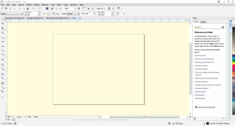
This week we were tasked in designing our project and laying it out in 2D and 3D drawings. To start my final project drawings, I needed the basic dimensions of the Samsung Galaxy S5 so I could determine how big my case needed to be to hold the phone. Dimensions were found off of the following page: Samsung Dimensions. Within my engineering school experience, I am most use to programs like AutoCAD and Solidworks. But the licenses for these programs can get pretty expensive, so I wanted to try out some of the other programs suggested by Fab Academy as well as some suggested by the local students here in Alaska. After some research, I decided to go with the program CorelDraw. CorelDraw has a nice layout and was fairly easy to pick up. One of the things I did like about it was it provided hints/tips when you clicked on one of the tools. This made it very easy to pick up and use as a first time user. Figure 1 shows the layout of CorelDraw when you start the program up.
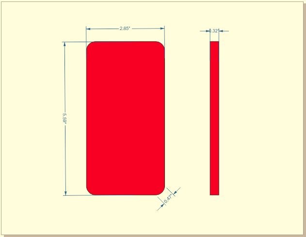
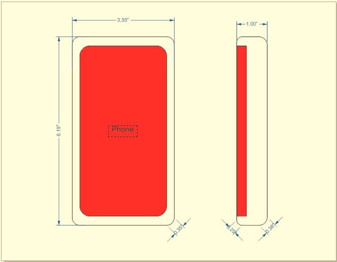
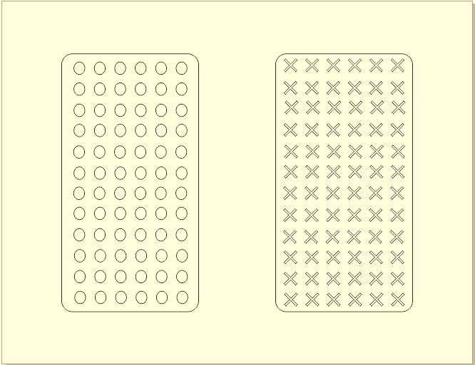
Using this program I drew up the basic dimensions for the Samsung Galaxy S5 as shown in Figure 2. From this I was able to draw up the size of the case I wanted for now, shown in Figure 3. An idea I had was to have casings on the back that you would be able to snap in and out to be able to change the design on the back. A couple of the design I have come up with are shown in Figure 4.
Figure 1: Layout of CorelDraw
Figure 2: Basic Dimensions of Samsung Galaxy S5
Figure 3: Basic Dimensions of LED Case
Figure 4: Preliminary Designs for Back of Case
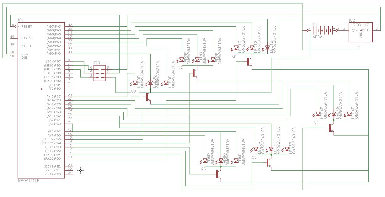
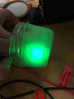
I also wanted to layout my basic schematic for the circuit that would control the LEDs. The program I used was called Eagle. This program allows you to download libraries of components and then lets you choose which components you want in your circuit. With the help of Kadin, he let me know which components I would need in my circuit and how it would need to be laid out since I have little knowledge with this type of stuff. In the schematic, Figure 5, shows a microcontroller that has six RGB LEDs connected to it. I chose to have six after testing a similar LED here in the lab within an opaque object. This image is shown in Figure 6.
Figure 5: Schematic of Electrical Design for LED Phone Case
Figure 6: Test LED in an Opaque Object
Now it was time to model my phone case using a 3D program. After watching Dr. Neil's Academy video from this week, one suggested program was Creo. I decided to give this program a shot. It did take a long time to download, had to leave the computer on downloading the program overnight, but I'm happy I waited. Through my engineering school career, I was most used to the 3D program SolidWorks. I was pleased that Creo was pretty much layed out the same way, with subtle differences. It was an easy program, for me, to pick up. This program is a parametric program that allows the user to design 2D drawings then extrude them so that they become a 3D model. I first started with the basic rectangle case and extruded it up to the desired height. After this I created a new sketch on the front face and sketched out the inlay for the phone. I then used the extrude cut feature that removes material from the model and extruded the cut down to the size of the phone. I did the same thing for the back design case. I then created a basic phone part to that will sit as the phone in the case as well as the design for the back. Creo also has an assembly feature that allows you to create an assembly from different parts. Using this I imported all the parts into Creo and mated them until they were a full assembly.
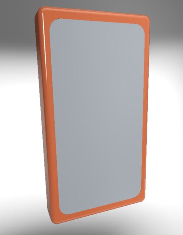
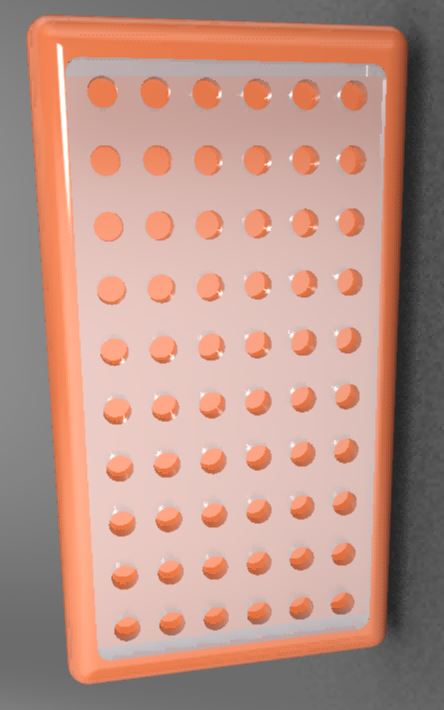
With the 2D drawings from CorelDraw, I was able to mock up a case and the basic phone in Creo as shown in Figure 7. My idea is that the case would be a rubber or silicone case in which the circuit board and LEDs would lay out in the case behind the phone. A button would be rigged up on the case that would control the LEDs. One push of the button would turn on all the red LEDs, the next would turn on all the green LEDs, and the next would turn on all the blue LEDs. A fourth push of the button would cycle randomly through the different LEDs. As mentioned befor, I wanted to have the option for the user to change the backing on the case. A rendered image of the 3D model with one of my designs for the back is shown in Figure 8. This back would be laser cut and be able to snap into the back of the case.
Figure 7: Basic 3D Rendered Image of Phone and Case Assembly
Figure 8: 3D Rendered Image for One Design of Back of Case